 ar
ar bg
bg hr
hr cs
cs da
da nl
nl fi
fi fr
fr de
de el
el hi
hi it
it ko
ko no
no pl
pl pt
pt ro
ro ru
ru es
es sv
sv tl
tl iw
iw id
id lv
lv lt
lt sr
sr sk
sk sl
sl uk
uk vi
vi et
et hu
hu th
th tr
tr fa
fa ms
ms hy
hy ka
ka ur
ur bn
bn mn
mn ta
ta kk
kk uz
uz ku
ku
load cell wiring diagram
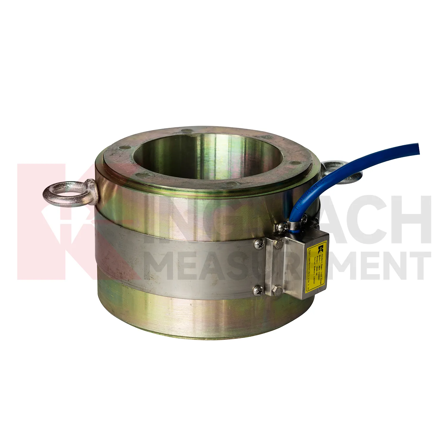
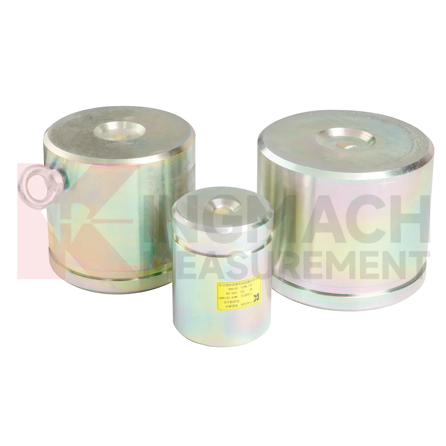
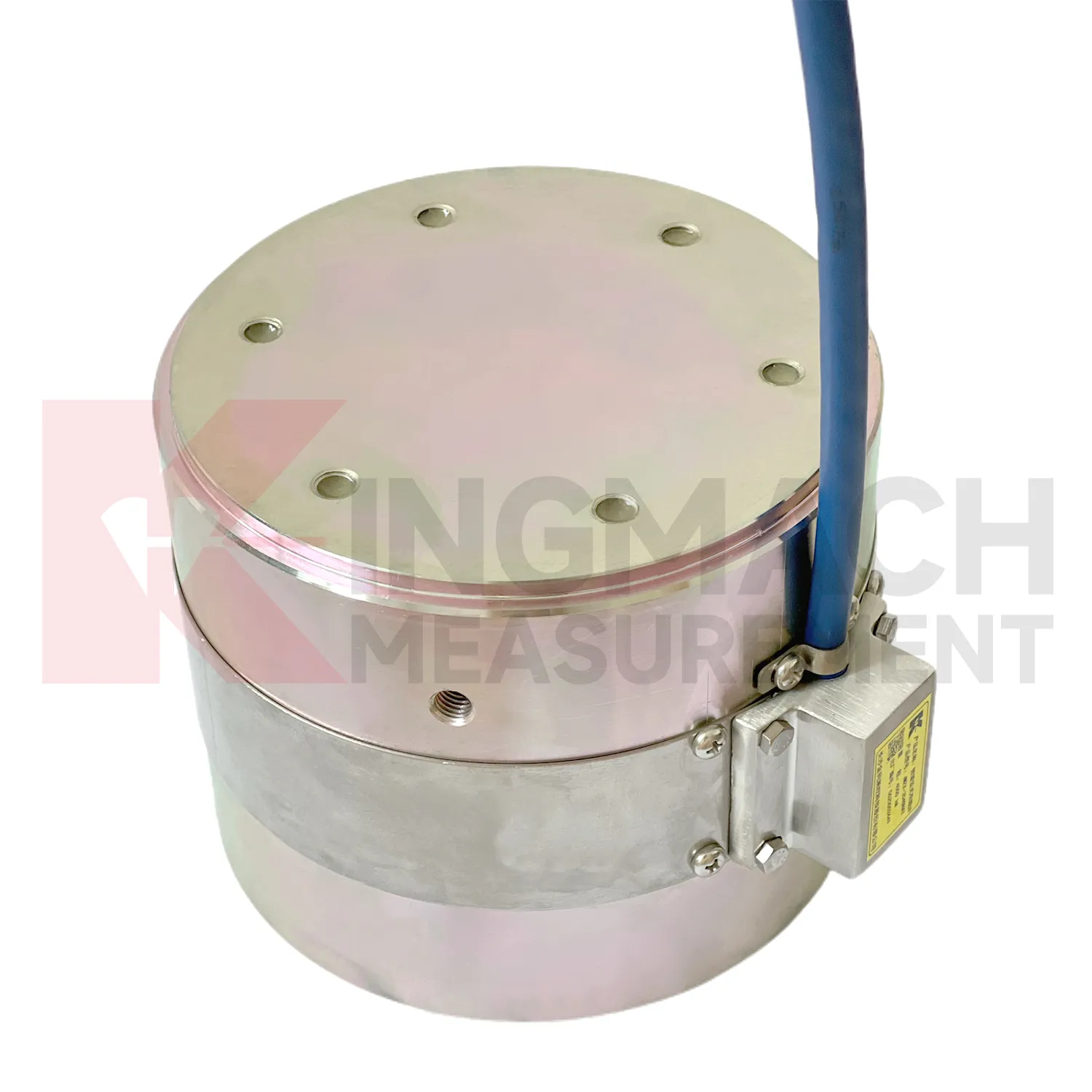
Kingmach load cell wiring diagram products are built for projects that need force data with a clear technical trail. The hollow load cell JMZX-3XXXHAT uses an annular multi-string elastic steel structure and is listed from 500 kN to 8000 kN, with 0.1 kN sensitivity on the 500 kN model and 1 kN sensitivity on larger models. Its product file also lists a 50 year design life, digital output, automatic temperature correction, waterproof durability, and storage for 800 measurement records. Those details are relevant in bridge cable force monitoring, anchor testing, and long term structural health monitoring, where the same point may be checked for many years. Kingmach, based in Changsha, supplies sensors with readouts, data loggers, DTUs, and software platforms, so the measuring point can be connected to a wider monitoring network. For a project team, the important value is not a catalog claim. It is the ability to identify the sensor, read the same force channel consistently, compensate temperature influence, and keep a documented record when access becomes difficult after construction. For brand context, Kingmach Measurement & Monitoring Technology Co., Ltd. works from Changsha, Hunan, and its product pages group load sensing with structural health monitoring, engineering monitoring sensors, readouts, data loggers, instrumentation cables, and visualization software. That catalog context matters because a force sensor is often purchased with the equipment needed to read and archive it.
Application of load cell wiring diagram
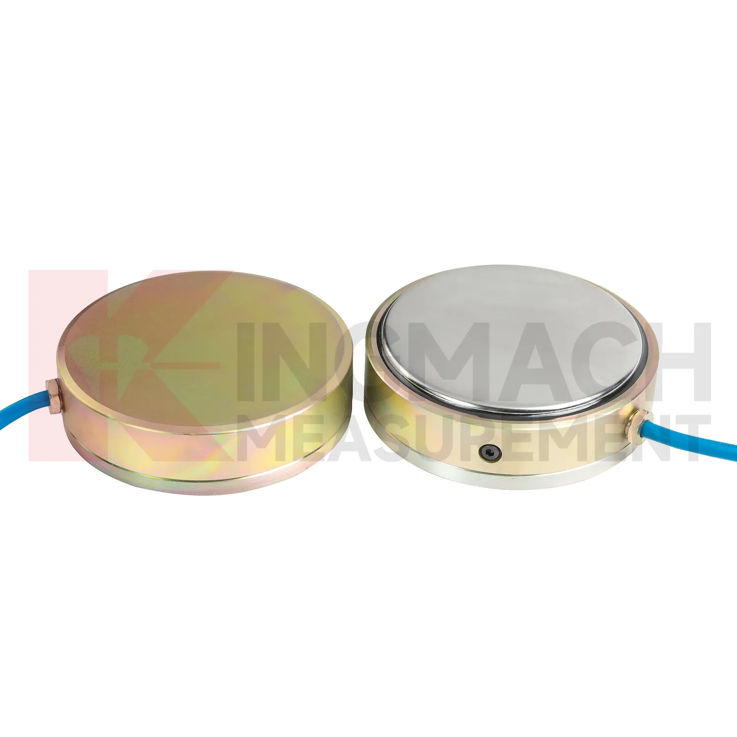
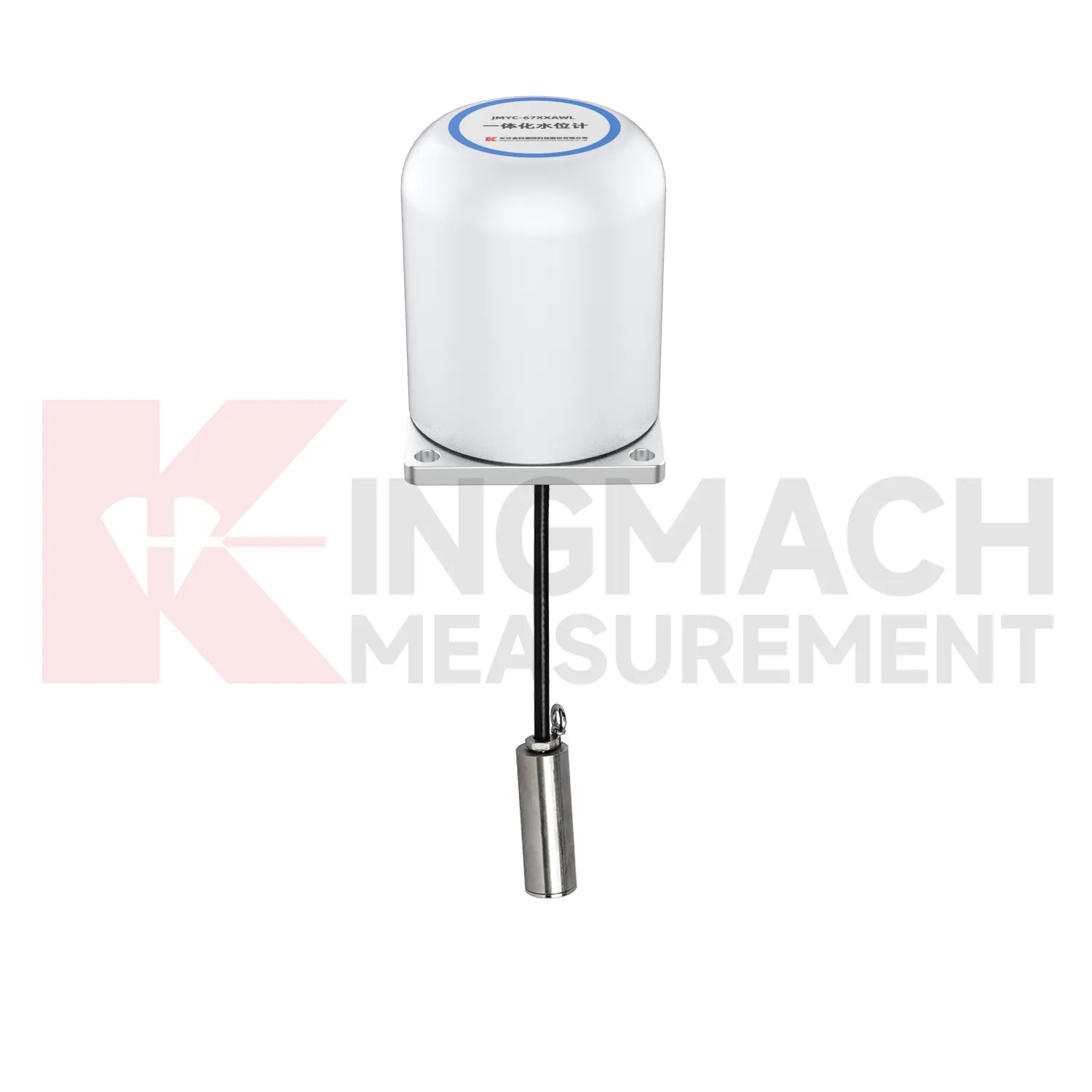
In slope, embankment, and retaining wall projects, load cell wiring diagram helps monitor anchor force, slide resistant pile load, earth pressure, and stress change after rainfall or groundwater variation. The practical pain point is that visible slope movement may arrive late, while load and pressure trends may start earlier. Earth pressure cells in the Kingmach range are listed from 0.3 MPa to 8 MPa, with 0.001 MPa resolution, 0.5%FS pressure accuracy, and ±0.5°C temperature accuracy. Hollow load cells for anchor force cover 500 kN to 8000 kN and include temperature correction and waterproof construction. These parameters support long term points in buried, wet, or exposed conditions. Force data should be reviewed with inclinometer, settlement, water level, rainfall, and crack observation records. If anchor force drops while displacement increases, the project team has a different problem than a temporary pressure rise after rain. The instrumentation plan should therefore connect each load point to the ground behavior it is meant to explain. On slopes, cable routes should be protected against rockfall, drainage works, vegetation clearing, and surface runoff. Those mundane details matter because a broken cable can look like a dramatic geotechnical event if the hardware is not inspected first.
The future of load cell wiring diagram
As monitoring standards become more detailed, load cell wiring diagram will be expected to support both engineering judgment and audit trails. Owners want to know whether a force change is real, when it began, how it compares with design stages, and what action followed. Kingmach load products already include technical features such as 0.5%FS precision on major force models, temperature correction, waterproof construction, direct kN display on axial force meters, and stored measurement records on smart designs. Future systems can tie these details to inspection workflows, maintenance orders, and asset management platforms. That means a load reading will not sit alone in a spreadsheet. It will connect to the sensor model, calibration certificate, installation photo, cable route, alarm history, and nearby movement data. Wireless links and AI screening may speed review, but the foundation remains disciplined measurement. The future belongs to force monitoring records that can be checked, repeated, and understood years after installation.
Care & Maintenance of load cell wiring diagram
For load cell wiring diagram used in bridge cable or anchor monitoring, maintenance should focus on the load path and the environment around the sensor. Hollow load cells list 500 kN to 8000 kN ranges, temperature correction, waterproof durability, and 800 stored measurement records on smart models. These features support long term observation, but they do not replace site checks. During installation, make sure the washer, bearing plate, anchor head, and sensor axis are properly seated. Record the first stable force after locking and keep the temperature reading with it. During operation, inspect cable protection, connector sealing, corrosion exposure, and any change near the anchor zone. Compare force records after seasonal temperature shifts, heavy traffic periods, maintenance work, or extreme weather. If one point changes while nearby points remain stable, check the bearing surface and wiring before treating the reading as structural behavior. A clean maintenance log helps separate sensor issues from real force redistribution.
Kingmach load cell wiring diagram
load cell wiring diagram is not limited to weighing or lab testing. In Kingmach's project world, it is part of structural and geotechnical monitoring, where the object being measured may be a cable, a pier support, a pile, a retaining wall, a tunnel support, or a dam anchor. The instrument must survive rough installation and still return a clear force or pressure value. Capacity, sensitivity, accuracy, overload allowance, waterproofing, and temperature behavior all affect whether the data can be trusted months later. A sensor with the wrong range may flatten important changes or overload during construction. A sensor with poor protection may drift after water enters a connector. A sensor with unclear calibration records may create doubt during acceptance. The better approach is to match the instrument to the loading path and the reading method at the same time. That keeps procurement, installation, and data review working from the same assumptions. Those details keep the instrument useful after the original installation crew has left the site.
FAQ
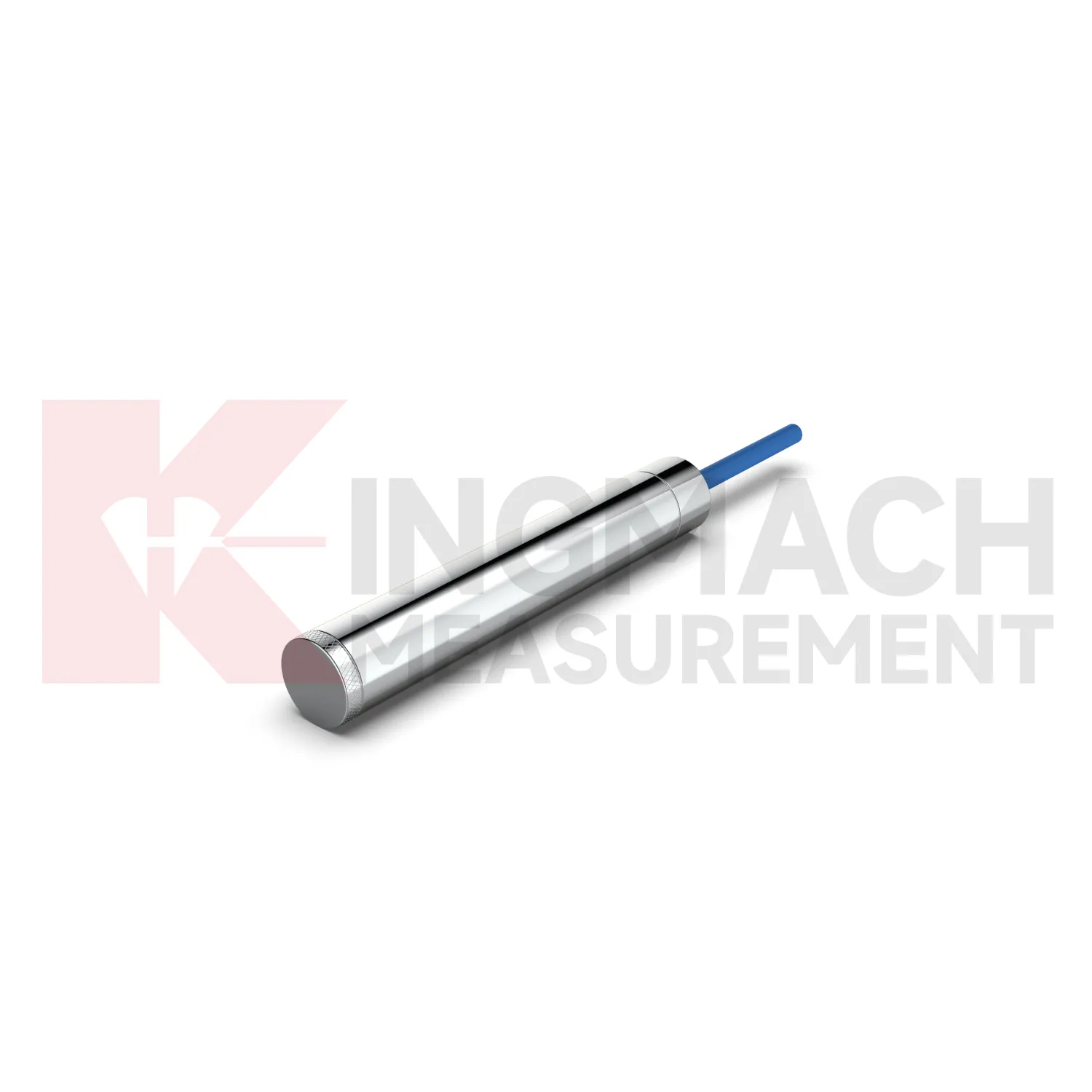
Q: When is a solid load cell wiring diagram more suitable than a hollow type? A: Solid models are commonly used for compression load, pile load testing, bridge pier support checks, and heavy bearing capacity measurement. Q: What specifications does the Kingmach solid load cell list? A: The JMZX-35XXHAT line lists 1000 kN to 10000 kN ranges, 0.1 kN resolution, 0.5%FS precision, and -30°C to 80°C working temperature. Q: How much overload margin is listed? A: Product information lists 20 to 50%F.S. range overload and 300 to 400%F.S. failure overload. Q: What installation errors affect accuracy? A: Eccentric loading, uneven bearing plates, side load, cable pulling, and missing zero records can all distort results. Q: What records should be kept for acceptance? A: Keep calibration coefficient, model, serial identity, load stages, temperature, zero value, and readout setting.
Reviews
Joshua Clark
We ordered a full monitoring solution including sensors and data loggers. Everything works seamlessly together. Great supplier!
David Wilson
We purchased displacement transducers and settlement sensors, and the quality exceeded our expectations. Easy installation and reliable performance.
Latest Inquiries
To protect the privacy of our buyers, only public service email domains like Gmail, Yahoo, and MSN will be displayed. Additionally, only a limited portion of the inquiry content will be shown.
Amelia***@gmail.comSingapore
Hello, I am looking for visualization software for monitoring system data analysis. Please let me kn...
Mia***@gmail.comNetherlands
Dear team, we are interested in your readouts & data loggers compatible with multiple sensors. Do yo...